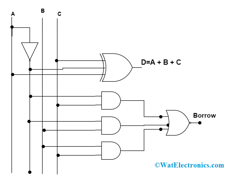
Logic Circuit Diagram Of Full Subtractor
Subtractor half logic gates Subtractor verilog circuits modeling Full subtractor logic diagram and truth / 4 bit binary adder subtractor
Verilog Code for Half and Full Subtractor using Structural Modeling
Combinational logic circuits : definition, examples, and applications Half subtractor Adder subtractor logic
Subtractor logic adder outputs inputs circuits geeksforgeeks binary
Adder subtractor block writing blargh prompts prompted student own look writer notSolved build the adder-subtractor circuit from page 18 from Combinational subtractor circuitsVerilog code for half and full subtractor using structural modeling.
Writer’s blargh (prompts for student writing, prompted by my own writer .

Combinational Logic Circuits : Definition, Examples, and Applications

Writer’s Blargh (prompts for student writing, prompted by my own writer

Half Subtractor - Truth table & Logic Diagram | Electricalvoice

Full Subtractor Logic Diagram And Truth / 4 Bit Binary Adder Subtractor

Verilog Code for Half and Full Subtractor using Structural Modeling
